 Before mounting systems are allowed to be installed, they must comply with corresponding standards, including EN 1991-1-4. Beside all the specifications regarding statics, materials, etc., this standard, including the national annex, contains specific information about wind loads to which PV systems and their mounting systems on roofs are exposed. In times of increasingly strong storms and even hurricanes this is indispensable for safety and must be included in the development. That is why the solar industry relies on so-called wind tunnel tests to keep the ballast of roof-penetration-free flat roof systems as low as necessary. In this blog entry, we explain how these tests are structured and what needs to be taken into account.
The fact is, for roof-penetration-free flat roof systems like our IBC AeroFix, the ballasting must be optimally calculated so that the system is placed aerodynamically and can withstand strong winds without any problems. The key to this is wind tunnel testing. This is also recommended by the German Institute for Building Technology in their DIBT guideline “Notes for the manufacture, planning and execution of solar systems”. There are two types of wind tunnel tests that are permissible according to Euronorm 1991-1-4:
- wind tunnel tests according to the WtG guideline
- recognised numerical methods (computer programs)
The prerequisite for this is that the structure and natural winds are modelled accordingly to determine loads and system reactions.

The test procedure for IBC SOLAR mounting systems
At IBC SOLAR, we have our aerodynamic PV systems (AeroFix and AeroFlat) tested at an institute that conducts wind tunnel tests in calibrated boundary layer wind tunnels: The I.F.I. Institute in Aachen, Germany.
This institute has been in existence for over 30 years and has two boundary layer wind tunnels and a measuring system for 380 simultaneous measuring points.
The test set-up in the wind tunnel
A typical set-up of a boundary layer wind tunnel looks as follows:
The wind is generated by 6 axial fans with 22 kW electric motors. In a 10 m long run-up section, the wind becomes turbulant and then hits a 1:50 scale model of the building and the PV system. The test section of the wind tunnel has a total length of 4 m, in which the measurements are carried out. At the end of the wind tunnel there is another 4 m long run-out section.

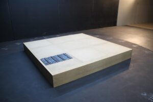
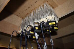
The model structure is embroidered with 360 measuring points in order to recognise what type of wind conditions have an effect on the system. At the same time, these are measured accordingly. The values on the top and bottom of the module are determined and recorded on a computer.
After the test has been carried out, the manufacturers receive a certificate for the tested, aerodynamic mounting system as well as a calculation tool with the help of which the wind influences on the system can be determined. This way, the ballast can be installed in the right place.
Difference to other flow measurements
Measurements of wind flows are used in various business segments. For example, in aeronautical and automotive engineering. However, the type of incident flow is completely different here compared to building aerodynamics. Aeronautical and automotive engineering involve so-called uniform low-turbulence inflows. Tests from these segments can therefore not be used for building aerodynamics, which is why specially developed tests are needed and exist.